ABSTRACT
Compliance with EEC directives and international standards on product safety is mandatory for those who operate in the food industry. Current legislation on food packaging calls for the producers to identify the equipment critical control points in order to put them under control during the different production phases. A maintenance process, intended to maintain the equipment criticalities under control, is mandatory to insure equipment reliability, and necessary if negative interactions between equipment and food product are to be avoided. Since a machine failure can have such a great impact on public health and on the whole manufacturing company, all the conceivable reasons for equipment failure must be identified and monitored to eliminate possible threats to human health. The equipment Critical Control Points (CCPs) must be identified and Critical Limits (CL) specified for each control measure at each CCP. For this reason the maintenance design process must be able to identify quantity variations, to compare them with target levels, to ensure that critical limits are met. For critical operational or production practices that are directly linked to biological, chemical, and physical hazards, potential deviations need to be identified together with critical limits. The periodic measurement or observation of CCPs is mandatory and necessary to determine whether a critical limit or target level has been met. The monitoring procedure must be able to detect loss of control at the CCP to identify potential and functional failures. Unsterility cases and food product safety problems often result from lack of maintenance control via automatic devices for monitoring critical parameters like temperature, flow, concentration, pressure, etc. It is suggested that the way to carry out the quantitative and qualitative analysis of food equipment criticalities is to ensure that all conceivable critical points that may result in food product contamination are put under control.
INTRODUCTION
Effective maintenance is based on the ability to identify the real maintenance needs of equipment through a system for gathering reliable information on the lifetimes of that equipment and of its components. The identification of both potential failure and functional failure – of a component or of a part of the machine – is an essential task if the variables that determine the occurrence of these two events are to be identified. Moreover, the qualitative analysis of failures enables the critical functions of a system to be kept under control. Lack of a maintenance system designed to keep the process under control may result in heavy loss of profit, and fall in market share, due to poor food product safety and quality. Below are some pointers on how to manage some of the critical steps in defining an effective maintenance programme.
GATHERING FAILURE INFORMATION THROUGH A FAILURE REPORTING AND CORRECTIVE ACTION SYSTEM (FRACAS)
FRACAS is a continuous improvement system utilizing a closed-loop feedback in which data on the failures of assets and equipments are recorded. These data are then reviewed and analyzed -considering such factors as Failure Rate, Mean Time Before Failure (MTBF), Mean Time to Repair (MTTR), Availability, Cost, etc. – in order to identify corrective actions that should be implemented and verified to prevent the failures from recurring. The FRACAS tool is particularly useful for identifying potential and functional failures and their impact on food product safety and company costs.
- A FRACAS system may attempt to manage multiple failure reports that are recorded by numerous individuals in different ways. FRACAS promotes reliability through considering a standard asset life cycle from cradle to grave (as shown in Figure 1).
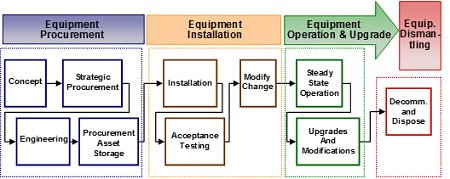
A FRACAS data base is directly linked to –
- Failure reporting
Through collecting and recording corrective maintenance information, data are consolidated into a central data logging system and failures are also ranked according to their criticality or severity. - Failure analysis
Detailed review of failure reports is done in order to capture historical data from the database of any related or similar failures. - Corrective actions
After identification of root causes for each failure, corrective actions to address equipment improvement are developed.
QUANTITATIVE FAILURE MEASURES THROUGH STATISTICAL ANALYSIS
Quantitative analysis can be used to “weight” a failure in order to gain knowledge about its importance and how it is distributed over time. Potential and functional failures must be measured through statistical tools for assessing their impact on the production activity. Statistical Process Control (SPC) allows the user to continuously monitor, analyze, and control the process. SPC is based on the understanding of variation and how it affects the output of any process, variation being the amount of deviation from a design nominal value. If we consider a failure (Y) as a function of different variables (X 1, 2, n), i.e. Y = F(X), then if we know the variations caused by the X’s it is possible, using SPC, to monitor the X’s first. Using SPC we can attempt to control the critical X’s in order to control the failure Y. To get an effective result we should be able to find the “vital few” X’s, and put them under control through SPC to achieve a desired result on Y.
Y can be defined as:
- Dependence
- Output
- Effect
- Symptom
- Monitor.
The variables X1, …Xn can be defined as:
- Independent
- Input
- Cause
- Problem
- Control.
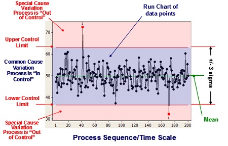
SPC is primarily used to act on “out of control” processes, but it is also used to monitor the consistency of processes creating products and services. A primary SPC tool is the Control Chart, a graphical representation of specific quantitative measurements of a process input or output. In the Control Chart, these quantitative measurements are compared against decision rules based on probabilities of occurrence of the actual measurement of process performance. Comparison of the decision rules and the performance data will highlight any unusual variation in the process, a variation that could indicate a problem with the process. The Standard Deviation for the data is calculated and two additional lines – placed ±3 Standard Deviations away from the Mean and called the Upper Control Limit (UCL) and the Lower Control Limit (LCL) – are added to the chart (see Figure 2).
The chart has three zones, i.e.
- between the UCL and the LCL, the zone of common variation,
- above the UCL, a zone of Special Cause variation,
- below the LCL, another zone of Special Cause variation, thus highlighting data points that do not fit the normal level of expected variation.
Such charts provide two basic functions:
- Monitoring the performance of the process, making it possible to track events affecting the process,
- Alerting the operator to the occurrence of any Special Cause variation.
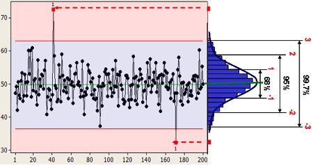
As indicated in Figure 3, 68% of the observations are expected to fall within ± 1 Standard Deviations (s.d.) from the Mean, 95% within ± 2 s.d., and 99.7%.within ±3 s.d.
- From a probability perspective, we would expect the output of a process would have a 99.7% chance of occurring within ±3 Standard Deviations from the mean, and only a 0.15% chance of falling either above or below the UCL or LCL. What this last occurrence means is that something special must have happened to cause a data point to be that far from the mean – a change in the preventive maintenance activities, an operator error, etc.
APPLICATION OF SPC TO POTENTIAL AND FUNCTIONAL FAILURES
Not every equipment stop can be due to a potential failure deviation or to a functional failure, that is why we need to establish tolerances on the nominal values to judge whether an equipment stop is to be considered as failure or not. During the equipment operation we can experience both potential and functional failures:
- Potential failure
Potential failures can be considered as variables depending on condition monitoring, hence a measurement such as a dimension, weight, and its unit of measurement can be specified. - Functional failures
Alternatively, a functional failure expresses the non-conformity or lack of availability of the equipment for production activity. In this case SPC uses attributes that are usually applicable to judgment of overall quality. In short, variables are measured while attributes are counted.
Special causes of variation are problems that arise in a periodic fashion. Examples are operator error, broken tools, and machine setting drift. They account for between 5 and 15% of quality problems and are due to factors that have “slipped” into the process, causing unstable or unpredictable variation. Removal of all special causes of variation yields a process that is in statistical control.
FAILURE DISTRIBUTION
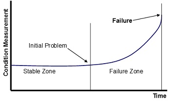
Using reliability data to predict the equipment performance generally involves assuming that the historical performance will reflect the current performance. Therefore, the best way to utilize this information to predict failures is by intelligent use of predetermined alarm limits. From analysis of numerous failure data on the mechanical groups, a general failure pattern, which takes the form shown in the Figure 4, becomes apparent.
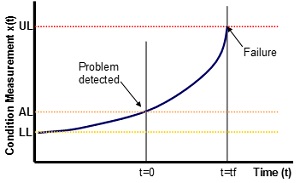
In the “stable zone”, measurements are simply varying around an average value. When they start to deviate from these values, it becomes apparent that a problem exists and the machine may have entered the “failure zone”. The setting of realistic alarm limits is achieved using SPC theory, such that when the condition monitoring measurements move outside the limits imposed (normally set at three standard deviations about the mean) the condition is registered as being “unstable” and the operation has entered the designated failure zone. Each zone is defined in terms of whether the condition monitoring measurement is inside or outside the alarm limits. On this basis, it is evident that the condition data acts as a switch or a go/not go signal. However, in order to make further use of the condition data, a model of the failure zone pattern is also introduced (see Figure 5).
The failure condition commences at the lower limit (LL), which is the averaged conditional value within the stable zone. The condition measurement X(t) increases until it is detected passing through the alarm limit (AL). Subsequently, at some time, t = tf, the upper limit (UL) is reached and the machine needs to be inspected or withdrawn from production. Inspection of actual failure case histories reveals that the failure pattern can be approximated to an exponential curve. Values for LL and AL are obtained from the SPC modelling of the stable zone. The estimate of UL is more problematical since it is the maximum possible level the machine is permitted to reach before actual failure occurs. The time “tf” is obtained by reference to reliability analysis of previous failures.
DETERMINING THE TASK INTERVAL

Since, as shown in the Figure 6, an inspection interval is based upon the time from potential failure to functional failure, a curve can be developed showing the time occurring from the onset of failure to functional failure. This time period is known as time (Tos) from onset.
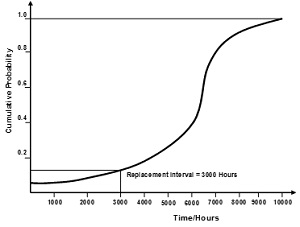
Figure 7 provides an example. The point on the slope at which a physical symptom (potential failure) appears being the beginning of Tos. The maximum inspection interval is Tos; to assure that an inspection to detect impending failure will occur between the appearance of potential and functional failure, inspection intervals must be shorter than Tos.
If an inspection fails to identify and correct the mechanical wear or symptom, there would be at least one more inspection before functional failure occurs. For that reason, for a critical machine parts whose failure might determine food safety risks, the inspection interval was established at 1/3 or 1/4 of Tos. Scheduling a replacement or overhaul task was an exercise based upon the curve shown in Figure 7. Since the probability of failure increases as a component’s age increases, the task interval was selected to provide an acceptable probability of failure. In this case, it was decided that replacement of the component should occur at 3,000 operating hours, where the probability of failure exceeded 0.15. When available data shows that failures are evenly distributed around the mean, the scheduled maintenance interval could be based on the MTBF.
QUALITATIVE ANALYSIS OF FAILURES
As soon as the different types of failure have been identified, through statistical and historical analysis, and potential and functional failures been weighted, we are ready to proceed with a qualitative analysis of the failures. The use of different quality tools will determine a clear understanding of the
- links between causes and effects,
- reasons behind each cause,
- link between each cause and the global equipment and manufacturing context,
- logical order of the events that produce a failure.
There follows a list of some of the quality tools normally used in a qualitative analysis of failures.
(i) Fault Tree and ‘What’s Different’ Analysis
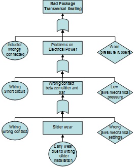
Fault Tree Analysis (FTA) establishes a connection between the different failure modes and a specific effect. Investigation to determine the underlying reasons for non-conformance to system requirements leads to the identification – necessary to define appropriate corrective actions – of non-conformance root causes. FTA is a technique that identifies all potential failure causes. It starts with a top undesired event, the system failure mode for which one is attempting to identify all potential causes. The analysis then sequentially develops all potential causes. Figure 8 is a simple example, showing how different causes behind a specific failure (potential or functional), in this case a bad package transversal sealing, were highlighted and linked together. The centre column shows the real cause that produces this failure and the lateral rows show the hidden causes or human errors. This technique facilitates the linkage of causes and effects in a logical order, giving a global view of the dynamic of the events that produce critical failures. More complex trees can be developed using OR and AND logic gates, and other operators and tools, to identify the potential failure causes and the relationships between them.
After mapping the fault tree, the implementation is needed of supporting techniques to better identify the true failure causes. ‘What’s Different’ analysis is a simple technique that identifies changes that might have induced the failures. Its basic premise is that the system has been performing satisfactorily until the failure occurred; so something must have changed to induce the failure. The analysis of possible changes covers all interacting factors, such as –
- system design,
- manufacturing practices and processes,
- change of suppliers,
- change of equipment operators,
- quality change in the hardware lots,
- various other factors.
As changes are identified they should be evaluated against the identified potential failure causes.
(ii) Root Cause Analysis and Cause Mapping
These two techniques tie problems into the global manufacturing organization context. Root Cause Analysis (RCA) is based on three fundamental questions, viz.
- What is the problem?
- Why did it happen?
- What will be done to prevent it?
RCA starts from the result or from the symptom of the problem, linking this to the underlying causes. However, starting an investigation with a single problem does not necessarily reflect the global nature of a failure, so ‘Cause Mapping’ can be employed to define problems within the context of the overall manufacturing goals. The Cause Map organizes the findings of any investigation into ‘effect’ boxes, on the left, and ‘cause’ boxes to their right. The causes, in turn, represent effects of other causes, again placed to their right. Thus, every box in a cause map can be viewed as both an effect and a cause at the same time. The fuel that drives the cause-map analysis involves ‘why’ questions, which link together the chain of events.
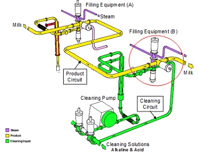
Figure 9 shows a cleaning circuit, the red circle indicating the valve that enables a liquid food product to flow on while the filling equipment (A) is in production and equipment (B) in the cleaning position.
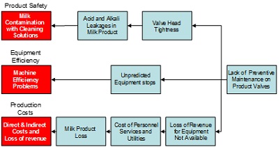
Because of lack of a reliable maintenance programme it has been found that cleaning solutions enter into the product pipes because product and cleaning valves of the filling equipment (B) have not been closing correctly. Small leakages of alkali and acid solutions come into contact with liquid food product if worn out valve heads are not replaced in due time. The Figure 10 RCA diagram identifies different causes that produce, as an effect, problems of –
- Product safety,
- Equipment efficiency,
- Production costs.
The connections existing between the various causes and their effects, and the sequences of events that they give rise to, are clearly shown. In addition to their use for trouble shooting, diagrams of this kind can be particularly effective when used as training material.
(iii) Ishikawa’s fishbone diagram
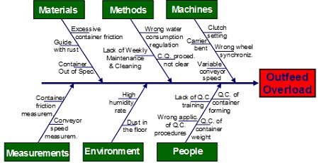
This technique helps to capture, visually, a problem and all its possible causes. The causes of a problem can be displayed, grouped into different root families: machines, methods, material, measurements, environment, people, and so forth. Ishikawa begins with a problem and then identifies its possible causes, in separate categories that branch off like the bones of a fish. Complementary to RCA, this analysis identifies one problem at a time and finds its causes, resulting in a global picture of the causes grouped into categories. It does not show the cause and effect relationship in its dynamic evolution, as RCA does, but creates a directory of causes underlying each problem, splitting them into families. Because, for instance, a training issue, grouped under ‘people’, can cause an operator to make an error that results in an equipment failure, grouped under ‘machinery’, the details of any investigation must be clarified, linking Ishikawa to RCA. Figure 11 shows an Ishikawa diagram applied to an outfeed overload mechanism of a filling machine. The different causes that produce an overload are listed under the main ‘four M’ branches.
On each branch, we list the causes that contribute to produce the problem, that is a single effect, and these causes are grouped under the main arms. This technique draws the attention to a single effect and to all the potential causes behind that effect. Despite it not being a dynamic representation of the evolution of causes and effects, it can be used as a complementary tool to depict all causes that produce a single effect. In conclusion, Fault Tree Analysis starts with a top undesired event that is the system failure mode for which one is attempting to identify all potential causes, and links all potential causes in a logic tree through events and gates. Root Cause Analysis and Ishikawa enable one to identify the potential causes that produce a failure, showing causes and effects and grouping them into families.
(iv) Five Why’s
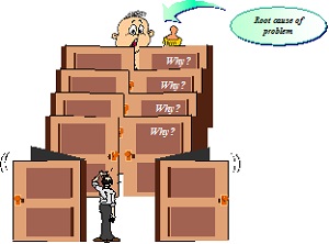
‘Five Why’s’ is complementary to Ishikawa. It begins with the end result, reflects on what caused that, and questions the answer five times. This elementary, but often effective, approach to problem solving promotes deep thinking through questioning, can be adapted quickly and applied to most problems. Figure 12 shows each ‘Why?’ as a door to be opened to enter into a specific context in order to discover its content.
There are three key elements for effective use of this technique, viz.
- Accurate and complete statements of problems,
- Complete honesty in answering the questions,
- Determination to get to the bottom of problems and resolve them.
The exercise is improved when applied by a team. There are five basic steps to conducting it.
a) Gather a team, develop an agreed problem statement, and decide whether or not additional members are needed to resolve the problem.
b) Ask the team the first ‘Why?’ Why is this or that problem taking place? There will probably be three or four sensible answers; record them all on a flip chart or whiteboard.
c) Ask four more successive ‘Why’s’, repeating the process for every statement on the flip chart or whiteboard. Post each answer near its ‘parent;. Follow up on all plausible answers. You will have identified the root cause when asking ‘Why?’ yields no further useful information.
d) Among the dozen answers to the last asked ‘Why?’ look for systemic causes of the problem. Discuss these and settle on the most likely one. Follow the team session with a de-briefing and show the result to others to confirm that they see logic in the analysis.
e) After settling on the most probable root cause and obtaining confirmation of the logic behind the analysis, develop appropriate corrective actions to remove the root cause from the system. To make effective use of this tool, stopping at symptoms, and not proceeding to lower-level root causes, must be avoided.
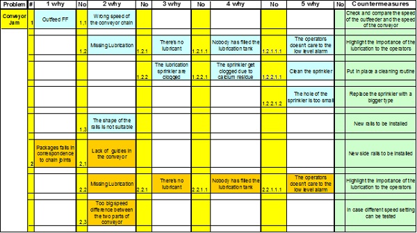
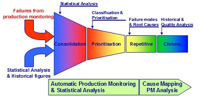
Figure 13 is derived from the application of this technique to a conveyor jam problem. Each single cause found becomes itself an effect of many other causes, and this process ends with the definition of countermeasures to avoid or correct the problem. The Failure Funnel shown in Figure 14, symbolises the result produced by the key methods and techniques (quantitative and qualitative) used. Through quantitative analysis we are able to identify and consolidate the different types of failure in a system.
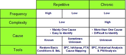
Through qualitative analysis we define the relationships between causes and effects in the specific context, and then, as result, we are able to prioritize and classify the failures. Table 1 summarizes the repetitive and chronic failures, showing their frequency, complexity and the potential causes, with the main findings coming from quantitative and qualitative analysis.
About the Author
Dr. Sauro Riccetti has carried out research on maintenance and process engineering in the food industry. His experience in Tetra Pak Italy, as Training Manager, Customer Service Director and Business Development Director, and his involvement in improvement projects for the food industry have enabled him to gain a wide experience in maintenance and process engineering in that sector. He is also Adjunct Lecturer, teaching automatic machines for the food industry, at the University of Bologna.

