ABSTRACT
Laser cladding is an additive process wherein a laser source is used to melt metal-based powder or wire on to a metal substrate. The result is a thick metal or metal matrix composite coating (of about 1 mm thickness) of a high quality; it has an excellent bonding to the substrate and is completely dense. The laser cladding process enables the treatment of heat sensitive materials and deformation sensitive components, which cannot be processed by conventional techniques like surface welding. The technique is increasingly being used in industry as a pro-active technology for corrosion and wear protection and as a reactive technology for repair of worn components. In both aspects, laser cladding is a technology contributing to cost-effective maintenance. Various research efforts are devoted to customised coating development with the aim to reduce maintenance. The state-of-the art, advantages and limitations of laser cladding as a repair and coating technique are discussed. The capabilities of the process are illustrated by industrial case studies performed by the Flemish Institute for Technological Research (VITO).
INTRODUCTION
The functionality of components can often be ameliorated by combining materials with optimised properties. The bulk material can be chosen for its formability, strength, stiffness and cost. The surface of this component can then be adapted to satisfy demands in the field of friction, wear, and corrosion.
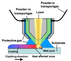
A possible process for optimising the surface of metal components is laser cladding [1, 2]. The process can also be used as a repair technique. During laser cladding additive material is supplied in the form of wire or powder to the substrate to be treated. A laser beam melts the additive material and a thin surface layer of the substrate, resulting in a coating with a typical thickness of 0.5-1 mm (see Figure 1). In most cases, powder is used as feedstock and transported in an argon gas flow. It is possible to use an additional protective gas flow to minimise oxidation during laser cladding. Due to the superficial melting of the substrate, a strong metallurgical bond is formed between substrate and coating. This is an important benefit compared to thermal spraying where only a mechanical bond is formed between the coating and substrate. Another advantage compared to thermal spraying is the higher powder yield, which is typical 75%. Thanks to the low and local heat input, laser cladding is very well suited for the treatment of heat sensitive materials and components, deformation is limited and the heat affected zone is small. Moreover, the high cooling rate during laser treatment results in coatings with a fine microstructure. After deposition, machining of the component to its final dimensions is mostly required. As laser source different types of lasers can be used, viz. CO2, Nd:YAG (neodymium-doped yttrium aluminum garnet), diode, disk or fibre laser. The first two are the most commonly used in materials processing by laser welding and cutting. However, there is currently a strong development in new, more compact and more efficient lasers, including the diode, disk and fibre lasers. The results presented in this paper are obtained using a diode laser as processing tool.
Laser cladding is a relatively new process, which is being used in industrial sectors like petrochemical, aerospace, machine and die building, automotive, energy production – to repair damaged high-value machine components like turbine blades, shafts, motors, etc., and to improve the corrosion and/or wear resistance of metallic components like tooling, pumps, valves, off-shore pipes, etc.
The possibilities of laser cladding as a repair and surface treatment technology in the energy production industry is illustrated with two case studies – the repair of a compressor shaft, and the repair of turbine wheels – carried out for the company Maintenance Partners, who are leaders in the Benelux area in the repair and modification of mechanical and electrical rotating machines.
EXPERIMENTAL SETUP
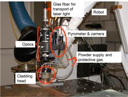
Figure 2 shows the experimental setup used for laser cladding in this study. It features a 3 kW fibre-coupled diode laser (Laserline) using specific optics to obtain a circular spot with a diameter of about 3.7 mm at the substrate. A Medicoat powder supply unit, which is commonly used for thermal spraying, is used. The powder is supplied in an argon gas flow to the coaxial cladding head. A CCD camera, which looks through a semi-transparent mirror coaxial with the laser beam, enables aligning of the cladding head to the area to be treated.
REPAIR OF COMPRESSOR SHAFT
The compressor shaft was made of martensitic stainless steel AISI 410 (DIN 1.4006 / X12Cr13). Near the end of the shaft an area with an axial length of 70 mm had been worn off. The total length of the shaft was about 3.7 m and the weight was about 1 ton. For laser cladding, stainless steel powder AISI 316L was used as feedstock. A coating with a total thickness of 2 mm was required. Since it was not possible to obtain a coating with a thickness of 2 mm after a single pass, multiple layers were applied on top of each other. The typical maximal layer thickness for a single pass was 1-1.2 mm. After laser cladding about 0.2 mm of the thickness needed to be removed to obtain a smooth surface.
Preliminary tests
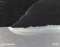
Before treating the shaft experiments were performed on a small bar to evaluate the quality of the coating in terms of absence of cracking, the degree of deformation of, and the bonding to, the substrate. To evaluate the deformation behaviour a bar with a diameter of 30 mm and length of 700 mm was clad at both ends over a length of 20 mm. The results of a run-out were satisfactory and showed a deformation of only 0.02-0,04 mm.
The cross section of the coating near the beginning is shown in Figure 3. No cracks in the coating or in the martensitic stainless steel substrate were present. Copper inserts were placed in key-seatings, which did not need to be treated, to prevent these being damaged by the laser beam. The stainless steel 316L material does not adhere to the copper and the copper insert could be easily removed after laser cladding.
Laser cladding of shafts
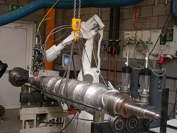
The same laser cladding parameters as used in the preliminary tests were applied during laser cladding of the shafts. The experimental setup is shown in Figure 4, the copper insert at the key-seatings being visible in the left hand image. Two layers of stainless steel were applied on top of each other. The shafts were machined afterwards and the repair was positively evaluated, exhibiting adequate thickness and good bonding of coating to substrate, minimal deformation induced by laser cladding, and no porosity in coating.
REPAIR OF COMPRESSOR WHEELS
Various compressor wheels were worn near the outer diameter. The wheels were made of 30CrNiMo8 steel in two separate parts connected to each other by mechanical fasteners. In between the upper and lower plates there were 17 blades. This construction made it impossible to use conventional welding to repair the wheels since the excessive heat input would result in distortion, which would eventually result in loosening of the upper from the lower plate. Another phenomenon observed when trying to repair the wheels by conventional TIG welding was the presence of cracks near the mechanical fasteners, which were located very close to the area being welded.
Preliminary tests
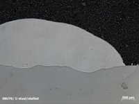
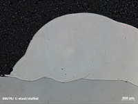
Prior to treatment of the wheels, laser cladding experiments with stellite 21 powder on a 30CrNiMo8 substrate were performed to evaluate the presence of cracks in the coating and in the heat affected zone of the substrate. No such cracks or large pores were observed after metallographic analyses (see Figure 5). The Vickers hardness of the stellite 21 coating after laser cladding was 450-460 HV (0.5 kg load).
Laser cladding of compressor wheels
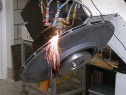
The setup used during laser cladding of the wheels is shown in Figure 6. The wheel was mounted on a rotational axis. To prevent damage of the blades the laser was not placed perpendicularly but at an off-axis position.
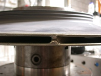
Figure 7 is a close-up of a wheel after laser cladding. At the outer diameter of the wheel about 13 laser cladding passes were applied to achieve an increase in diameter from 624 mm to 632 mm. The applied scan speed was 1000 mm/min. No cracking in the substrate or the coating was observed visually. After laser cladding and machining the wheels were evaluated by a spin test, rotating the wheels in vacuum at a speed of 20,000 rpm. All the treated wheels survived that test successfully.
CONCLUSIONS
- The local repair of a martenstic stainless steel compressor shaft by laser cladding proved to be successful thanks to the low heat input of the laser process and the high quality of the resulting laser-clad coating in terms of metallurgical bonding to the substrate and high coating density.
- Damaged compressor wheels have been repaired by laser cladding. The repair process proved to be successful after spin testing the wheels at 20.000 rpm in vacuum.
REFERENCES
[1] de Damborenea J, Surface modification of metals by high power lasers, Surf. Coat.Technol. 100–101, pp.377–382 (1998)
[2] Sexton C L, Byrne G, Watkins K G, Alloy development by laser cladding: an overview, J. Laser Appl. 13 (1), 2–11 (2001)
Authors’ contact addresses
Flemish Institute for Technological Research (VITO), Laser Centre, Boeretang 200, 2400 Mol, Belgium.
Maintenance Partners Heavy Duty nv, Vishoekstraat 6, Haven 1035, 2070 Zwijndrecht, Belgium

