ABSTRACT
In our May/June issue Ray explained how unbalance in rotating machinery – one of the commonest cause of vibration in rotors large and small – can be eliminated with the aid of the stopwatch feature of a mobile phone. In this second article, he explains more from his experiences in balancing.
INTRODUCTION
Where a machine has a rotor that can be regarded as ‘short’ then single-plane balancing is usually satisfactory. The previous article showed a method of balancing off-speed with the only instrument required being a stop watch (or that feature of a mobile phone). Balancing is not always the remedy for unacceptable vibration of a machine. Looseness and misalignment are other possibilities that should be checked. However, from long experience with a machine, the major recurring cause of an increase in vibration may be known to be unbalance. An example is a fan handling dirty gas that results in deposition on the blades or uneven erosion of them. It may be more economical to return the fan to acceptable vibration by balancing, at least in the short term, rather than by cleaning the deposit or replacing the worn blades.
SINGLE PLANE BALANCING USING AMPLITUDE AND PHASE
Many of the vibration analyser/data collectors common in industrial plants have a feature available to perform balancing, where the vibration signal at the frequency of rotation speed is shown and the phase angle relative to a reference point on the rotor indicated. The method is shown by the instrument and the mass required to balance is calculated and the position indicated. With such a capability, it is possible to lose the rationale behind the process.
The earlier manually- tuned analysers often included a stroboscope that was triggered to fire when the vibration was tuned to the frequency of rotation. With reference numbers around the shaft, the phase angle relative to a shaft could be found.
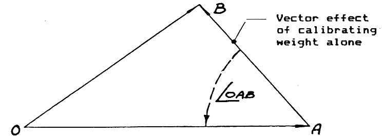
The sketch below shows the essence of this method. Three runs are usual: an original run, a trial run with a calibrating weight, and a final run to check the result before return to service. The required mass to balance and its location are given from a vector plot.
In a power station with 64 fan-type mills, balancing using this method was a regular activity as the blades became eroded non-uniformly around the rotor. Routine vibration monitoring would identify a mill with unacceptable vibration. A Work Request would be submitted. Next day, the mill would be available, shut down and isolated electrically to enable safe access.
Using chalk, numbers were marked around a visible section of shaft in line with the rotor blades. The mill was cleared to be run. An ‘original’ run enabled the vibration amplitude in displacement at the frequency of rotation to be measured, and the instrument’s stroboscope tuned to this frequency gave the matching phase angle, with the vibration probe held in line with the horizontal joint. The same orientation is of course needed for each run.
The original vector obtained was plotted to scale, as OA in the sketch.

The mill was again isolated for safe access. A calibrating mass was clamped firmly on the rotor on a blade at about 90 degrees behind the indicated high spot (Note: this angle may vary with the instrument used and if vibration velocity is used for amplitude).
The mill was restored to service and the calibrating run made. The resulting vector OB is drawn to scale. The size of the mass to balance and its fixing point was then determined. In this example, the mass to balance would be larger than the calibrating mass by OA/AB and fixed to a position rotated an angle OAB, the aim being to cancel out the initial unbalance vector.
The mill was then shut down and isolated, and the correction mass change made, in this case by flame-cutting mass from the blade leading edge. (These are simple machines with replaceable blades).
The mill was restored, and a check run made. If all was OK, the mill was cleared for normal service. (On one not-so-celebrated occasion, the author mistakenly gave the correction angle as 180 degrees out. Fortunately this was evident when the clamp used to restrain the rotor during balance mass change was removed, and the rotor slowly rotated to settle with the now extra unbalance “correction” mass at the bottom!).
INSTANT BALANCING
As can be seen from this description, the procedure above took all day, due mainly to the time taken to make the electrical isolations. Comparing the outcome of several balances, it was noticed that the amount of correction mass and required angle were similar between mills. A rule was therefore developed for these mills: remove mass at 72 degrees behind the indicated high spot at 10 grams per µm peak-to-peak of vibration. (This rule applied only to the particular balancing instrument used).
Numbers were painted permanently on the shaft. Now when a mill is detected with high vibration, original readings are taken, the mill is removed from service, isolated for safety, and the correction made. It is returned immediately afterwards, and such is the confidence in the method than a check run is not needed. The revised process takes much less time. Maybe this approach can be applied to your situation?
These fan-type mills are driven via a fluid coupling. These also needed occasional balancing. To access the rotor to make and observe the reference marks the coupling guard had to be lifted off with a mobile crane. This effort was eliminated by modifying each of the guards with a small hinged door.
OTHER METHODS
As shown in the table in my article in Issue 13.3, there are other methods where only a basic vibration level meter is available. Try a web search on ‘balancing by the 3-point method’ or ‘balancing by the 4-runs method’ for details.

